Products

6-22kV S13-M.RL Oil-Immersed Three-Dimensional Wound Core Distribution Transformer

1. Low Loss and Excellent Energy-Saving Performance
2. Low No-Load Current
3. Low Operating Noise
4. Strong Short-Circuit Resistance

Send Message

Product Introduction

  • The S13-M.RL series oil-immersed three-dimensional wound core distribution transformer adopts an advanced three-dimensional wound core structure, in which the three core limbs are arranged in an equilateral triangular configuration. This design ensures a more balanced three-phase magnetic circuit and effectively overcomes the structural and technological limitations of traditional laminated planar cores.
  • With this innovative structure, the transformer demonstrates significant advantages in lower losses, reduced noise, stronger short-circuit resistance, and higher operational stability.
  • Compared with the traditional S11 series transformers, the S13 series achieves an average 28.4% reduction in no-load loss, 70% reduction in no-load current, and 7–10 dB reduction in operating noise, providing remarkable energy-saving performance as well as considerable economic and social benefits.
  • With its optimized structure and reliable performance, the product is widely used in urban power grids, rural distribution networks, and industrial power distribution systems.

6-22kV-S13-M.RL-10

Application Scenarios

  • The transformer is suitable for three-phase, 50 Hz, 10 kV power distribution systems, and is widely used in:
  • Urban power distribution networks
  • Rural grid reconstruction projects
  • Industrial and mining enterprise power systems
  • Power and lighting distribution systems

6-22kV-S13-M.RL-11

Product Features

  • 1. Core Structure
  • The transformer core adopts a three-dimensional wound core design with a symmetrical three-phase three-limb structure, ensuring a balanced magnetic circuit.
  • The core is wound from high-quality cold-rolled silicon steel strips using specialized winding equipment and is subjected to vacuum annealing treatment to eliminate internal stress and improve electromagnetic performance. The core surface is coated with epoxy resin paint, providing excellent moisture resistance and corrosion protection.
  • 2. Winding Structure
  • The windings are made of high-purity low-oxygen copper conductors.
  • The low-voltage winding adopts a double-layer or four-layer structure.
  • The high-voltage winding adopts a multi-layer cylindrical structure.
  • Reasonable oil ducts are arranged between windings, and high-density insulating materials are used to enhance insulation performance, heat dissipation capability, and short-circuit mechanical strength.
  • 3. Transformer Body Structure
  • The transformer body is supported and fixed by high-strength insulating materials, and all fasteners adopt anti-loosening designs, ensuring structural stability during operation.
  • 4. Oil Tank Structure
  • The transformer adopts a fully sealed corrugated oil tank structure, eliminating the need for a conservator. The corrugated fins not only enhance heat dissipation but also compensate for oil volume changes caused by temperature variations.
  • The tank cover is equipped with an oil level indicator and pressure relief valve, allowing convenient monitoring of oil level and safe pressure release in case of internal faults.

6-22kV-S13-M.RL-12

Manufacturing Process Features

  • The product is manufactured using advanced production processes and specialized equipment, including core winding machines and automated corrugated oil tank production lines. These processes significantly improve product quality and manufacturing efficiency.
  • Through optimized structural design and manufacturing technology, the transformer achieves enhanced mechanical strength, higher reliability, and longer service life.

Product Parameter

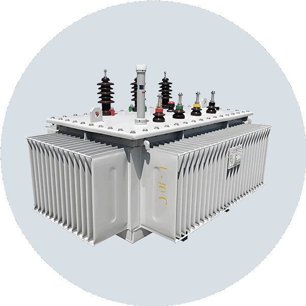
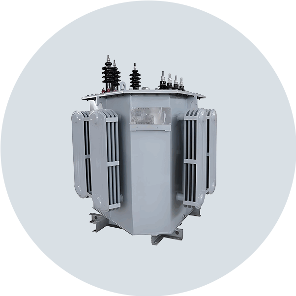
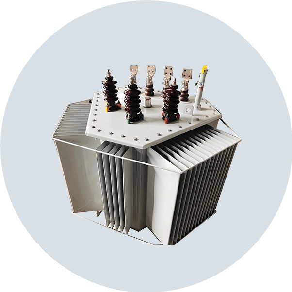
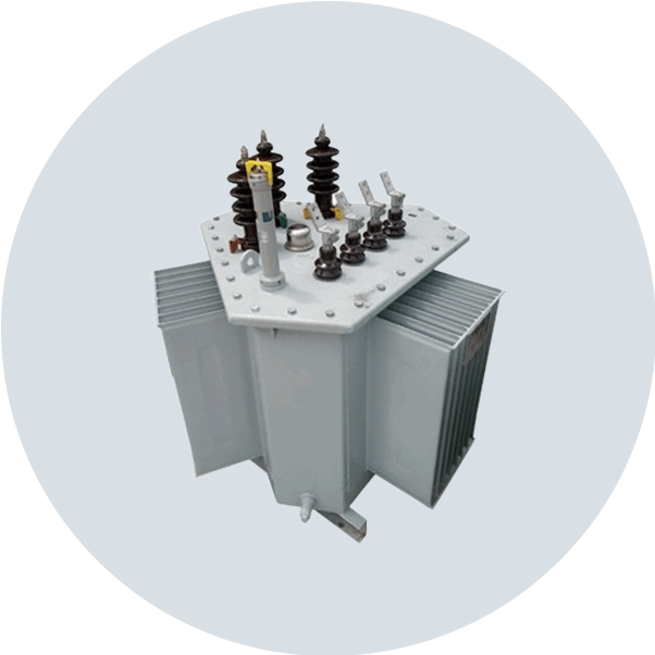
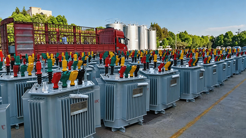
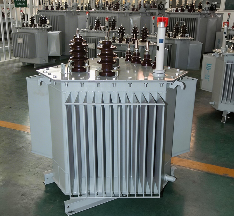
Technical Parameters of S13-M.RL Oil-Immersed Three-Dimensional Wound Core Distribution Transformer
Rated Capacity (kVA)    Voltage Combination and Tap Range Vector Group No-Load Loss (kW) Load Loss (kW) No-Load Current (%) Short-Circuit Impedance (%)
High Voltage (kV) HV Tap Range Low Voltage (kV)
30

6

6.3

10

11

±5%

±2×2.5%

0.4

Dyn11

Yyn0

0.08 0.63/0.60 0.3

4.0

4.5

50 0.10 0.91/0.87 0.24
63 0.11 1.09/1.04 0.23
80 0.13 1.31/1.25 0.22
100 0.15 1.58/1.50 0.21
125 0.17 1.89/1.80 0.20
160 0.20 2.31/2.2. 0.19
200 0.24 2.73/2.60 0.18
250 0.29 3.20/3.05 0.17
315 0.34 3.83/3.65 0.16
400 0.41 4.52/4.30 0.16
500 0.48 5.41/5.15 0.16
630 0.57 6.20 0.15
800 0.70 7.50 0.15
1000 0.83 10.30 0.14
1250 0.97 12.00 0.13
1600 1.17 14.50 0.12
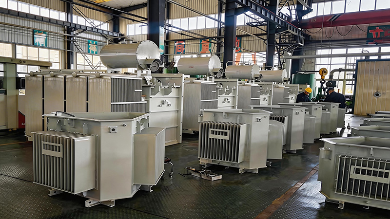
Note: Transformers can be customized to operate under special service conditions according to user requirements.

Inquiry

    Send MESSAGE

      Contact Us

      Copyright © 2026 Henan Believe Electric Co., Ltd.

      Home WhatsApp Mail Inquiry